Pens and Brushes
To manipulate the appearance of the graphics (lines, curves, shapes) drawn with Graphics Mill for .NET, special objects—pens and brushes—are used. Pens exposes settings for lines, curves, and outlines of the closed shapes. Brushes contain settings for filling closed shapes (rectangles, ellipses, polygons, etc).
Let's examine these classes more closely.
Pen
The Pen class specifies a number of settings for the outlines:
- Pen color. Note, it does not support transparency information, so alpha channel of the color will be ignored. Specified by the Color property.
- Pen width. Minimum pen width is 1. Specified by the Width property.
- Dash style. You can draw solid lines (or curves) as well as use several predefined
patterns of dots and dashes. Specified by the DashStyle property.
Note
If you use GdiGraphics for drawing, keep in mind that the dash style is changed, only if line width is equal to 1. This is a limitation of GDI.
- Start cap. When an opened figure or a line is drawn, you can specify how to draw the cap— it may be an arrow, a circle, a square, and so on. Specified by the StartCap property.
- End cap. The same, but for the end cap. Specified by the EndCap property.
Note
If you use GdiGraphics for drawing, keep in mind that the StartCap value will actually be replaced with the EndCap value. This is a limitation of GDI.
- Pen alignment. This property is meaningful when drawing closed shapes with pen width greater than 1. It specifies what should be treated as coordinates of the line: center of the drawn line or outer border. Specified by the Alignment property.
- Line join type. When drawing polyline, the junction of lines can be drawn in different ways—rounded, sharp-edged, beveled, etc. Specified by the LineJoin property.
- Limitation for mitered join. When line join should be mitered, this parameter specifies maximum length of the junction. Specified by the MiterLimit property.
Basic Examples
After you create an instance of the Pen class and specify desired settings, you can pass it to some of the drawing methods of the GdiGraphics class (for example, DrawLine). This way a line or a curve with necessary settings will be drawn.
The code example that demonstrates how to use the Pen class is below. It produces the image you can see at this figure:

Dim bitmap As New Aurigma.GraphicsMill.Bitmap( _
 Aurigma.GraphicsMill.RgbColor.White, 100, 60, _
 Aurigma.GraphicsMill.PixelFormat.Format24bppRgb)

Dim graphics As Aurigma.GraphicsMill.Drawing.GdiGraphics = bitmap.GetGdiGraphics()

Dim bluePen As New Aurigma.GraphicsMill.Drawing.Pen(Aurigma.GraphicsMill.RgbColor.Blue, 8)

graphics.DrawLine(bluePen, 10, 55, 90, 5)

Dim redPen As New Aurigma.GraphicsMill.Drawing.Pen(Aurigma.GraphicsMill.RgbColor.Red, 8)

graphics.DrawLine(redPen, 10, 5, 90, 55)
Aurigma.GraphicsMill.Bitmap bitmap = new Aurigma.GraphicsMill.Bitmap(
    Aurigma.GraphicsMill.RgbColor.White, 100, 60,
    Aurigma.GraphicsMill.PixelFormat.Format24bppRgb);

Aurigma.GraphicsMill.Drawing.GdiGraphics graphics = bitmap.GetGdiGraphics();

Aurigma.GraphicsMill.Drawing.Pen bluePen = new Aurigma.GraphicsMill.Drawing.Pen(
    Aurigma.GraphicsMill.RgbColor.Blue, 8);

graphics.DrawLine(bluePen, 10, 55, 90, 5);

Aurigma.GraphicsMill.Drawing.Pen redPen = new Aurigma.GraphicsMill.Drawing.Pen(
    Aurigma.GraphicsMill.RgbColor.Red, 8);

graphics.DrawLine(redPen, 10, 5, 90, 55);
You may notice that lines produced with GdiGraphics are not smooth. Also, there is no possibility to draw semitransparent lines. This problem may be resolved by using standard .NET drawing classes. Note, that these classes have some disadvantages compared to the GdiGraphics class. For more details, see the Comparison: GdiGraphics and System.Drawing.Graphics topic.
The code below demonstrates how to draw lines on a Aurigma.GraphicsMill.Bitmap object to create an images like on the following figure using GDI+ System.Drawing.Graphics class:

Dim bitmap As New Aurigma.GraphicsMill.Bitmap( _
 Aurigma.GraphicsMill.RgbColor.White, 100, 60, _
 Aurigma.GraphicsMill.PixelFormat.Format24bppRgb)

Dim graphics As System.Drawing.Graphics = bitmap.GetGdiplusGraphics()
graphics.SmoothingMode = System.Drawing.Drawing2D.SmoothingMode.AntiAlias

Dim bluePen As New System.Drawing.Pen(System.Drawing.Color.Blue, 8)

graphics.DrawLine(bluePen, 10, 55, 90, 5)

Dim redPen As New System.Drawing.Pen(System.Drawing.Color.FromArgb(200, 255, 0, 0), 8)
redPen.DashStyle = System.Drawing.Drawing2D.DashStyle.Dash

graphics.DrawLine(redPen, 10, 5, 90, 55)
Aurigma.GraphicsMill.Bitmap bitmap = new Aurigma.GraphicsMill.Bitmap(
    Aurigma.GraphicsMill.RgbColor.White, 100, 60,
    Aurigma.GraphicsMill.PixelFormat.Format24bppRgb);

System.Drawing.Graphics graphics = bitmap.GetGdiplusGraphics();
graphics.SmoothingMode = System.Drawing.Drawing2D.SmoothingMode.AntiAlias;

System.Drawing.Pen bluePen = new System.Drawing.Pen(System.Drawing.Color.Blue, 8);

graphics.DrawLine(bluePen, 10, 55, 90, 5);

System.Drawing.Pen redPen = new System.Drawing.Pen(
    System.Drawing.Color.FromArgb(200, 255, 0, 0), 8);
redPen.DashStyle = System.Drawing.Drawing2D.DashStyle.Dash;

graphics.DrawLine(redPen, 10, 5, 90, 55);
Pen Styling
With Graphics Mill for .NET, styling lines and curves is a really easy task.
First, you can easily change line caps. The following figure shows possible variants of line endings—round, flat and square respectively:
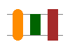
The source code below demonstrates how these lines are drawn:
Dim bitmap As New Aurigma.GraphicsMill.Bitmap( _
 Aurigma.GraphicsMill.RgbColor.White, 100, 70, _
 Aurigma.GraphicsMill.PixelFormat.Format24bppRgb)

Dim graphics As Aurigma.GraphicsMill.Drawing.GdiGraphics = _
    bitmap.GetGdiGraphics()

'Hotizontal line
Dim pen As New Aurigma.GraphicsMill.Drawing.Pen( _
 Aurigma.GraphicsMill.RgbColor.Gray, 1)
graphics.DrawLine(pen, 10, 20, 90, 20)
graphics.DrawLine(pen, 10, 50, 90, 50)

pen.Width = 15

'Line with rounded cap
pen.Color = Aurigma.GraphicsMill.RgbColor.DarkOrange
pen.EndCap = Aurigma.GraphicsMill.Drawing.LineCap.Round
graphics.DrawLine(pen, 25, 50, 25, 20)

'Line with flat cap
pen.Color = Aurigma.GraphicsMill.RgbColor.DarkGreen
pen.EndCap = Aurigma.GraphicsMill.Drawing.LineCap.Flat
graphics.DrawLine(pen, 50, 50, 50, 20)

'Line with square cap
pen.Color = Aurigma.GraphicsMill.RgbColor.Brown
pen.EndCap = Aurigma.GraphicsMill.Drawing.LineCap.Square
graphics.DrawLine(pen, 75, 50, 75, 20)
Aurigma.GraphicsMill.Bitmap bitmap = new
    Aurigma.GraphicsMill.Bitmap(Aurigma.GraphicsMill.RgbColor.White,
    100, 70, Aurigma.GraphicsMill.PixelFormat.Format24bppRgb);

Aurigma.GraphicsMill.Drawing.GdiGraphics graphics =
    bitmap.GetGdiGraphics();

//Hotizontal line
Aurigma.GraphicsMill.Drawing.Pen pen = new
    Aurigma.GraphicsMill.Drawing.Pen(Aurigma.GraphicsMill.RgbColor.Gray,
    1);
graphics.DrawLine(pen, 10, 20, 90, 20);
graphics.DrawLine(pen, 10, 50, 90, 50);

pen.Width = 15;

//Line with rounded cap
pen.Color = Aurigma.GraphicsMill.RgbColor.DarkOrange;
pen.EndCap = Aurigma.GraphicsMill.Drawing.LineCap.Round;
graphics.DrawLine(pen, 25, 50, 25, 20);

//Line with flat cap
pen.Color = Aurigma.GraphicsMill.RgbColor.DarkGreen;
pen.EndCap = Aurigma.GraphicsMill.Drawing.LineCap.Flat;
graphics.DrawLine(pen, 50, 50, 50, 20);

//Line with square cap
pen.Color = Aurigma.GraphicsMill.RgbColor.Brown;
pen.EndCap = Aurigma.GraphicsMill.Drawing.LineCap.Square;
graphics.DrawLine(pen, 75, 50, 75, 20);
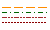
Another style option is the continuity of lines. Graphics Mill for .NET uses the System.Drawing.Drawing2D.DashStyle enumeration for specifying a dash style for the line. The following figure and the code sample demonstrate how to use available dash styles.
Dim bitmap As New Aurigma.GraphicsMill.Bitmap( _
 Aurigma.GraphicsMill.RgbColor.White, 100, 60, _
 Aurigma.GraphicsMill.PixelFormat.Format24bppRgb)

Dim graphics As Aurigma.GraphicsMill.Drawing.GdiGraphics = _
    bitmap.GetGdiGraphics()

Dim pen As New Aurigma.GraphicsMill.Drawing.Pen
pen.Width = 1

'Dashed line
pen.Color = Aurigma.GraphicsMill.RgbColor.DarkOrange
pen.DashStyle = System.Drawing.Drawing2D.DashStyle.Dash
graphics.DrawLine(pen, 5, 15, 95, 15)

'Line made of dash-dot patterns
pen.Color = Aurigma.GraphicsMill.RgbColor.DarkGreen
pen.DashStyle = System.Drawing.Drawing2D.DashStyle.DashDot
graphics.DrawLine(pen, 5, 25, 95, 25)

'Line made of dash-dot-dot patterns
pen.Color = Aurigma.GraphicsMill.RgbColor.Brown
pen.DashStyle = System.Drawing.Drawing2D.DashStyle.DashDotDot
graphics.DrawLine(pen, 5, 35, 95, 35)

'Dotted line
pen.Color = Aurigma.GraphicsMill.RgbColor.DarkRed
pen.DashStyle = System.Drawing.Drawing2D.DashStyle.Dot
graphics.DrawLine(pen, 5, 45, 95, 45)
Aurigma.GraphicsMill.Bitmap bitmap = new
    Aurigma.GraphicsMill.Bitmap(Aurigma.GraphicsMill.RgbColor.White,
    100, 60, Aurigma.GraphicsMill.PixelFormat.Format24bppRgb);

Aurigma.GraphicsMill.Drawing.GdiGraphics graphics =
    bitmap.GetGdiGraphics();

Aurigma.GraphicsMill.Drawing.Pen pen = new
    Aurigma.GraphicsMill.Drawing.Pen();
pen.Width = 1;

//Dashed line
pen.Color = Aurigma.GraphicsMill.RgbColor.DarkOrange;
pen.DashStyle = System.Drawing.Drawing2D.DashStyle.Dash;
graphics.DrawLine(pen, 5, 15, 95, 15);

//Line made of dash-dot patterns
pen.Color = Aurigma.GraphicsMill.RgbColor.DarkGreen;
pen.DashStyle = System.Drawing.Drawing2D.DashStyle.DashDot;
graphics.DrawLine(pen, 5, 25, 95, 25);

//Line made of dash-dot-dot patterns
pen.Color = Aurigma.GraphicsMill.RgbColor.Brown;
pen.DashStyle = System.Drawing.Drawing2D.DashStyle.DashDotDot;
graphics.DrawLine(pen, 5, 35, 95, 35);

//Dotted line
pen.Color = Aurigma.GraphicsMill.RgbColor.DarkRed;
pen.DashStyle = System.Drawing.Drawing2D.DashStyle.Dot;
graphics.DrawLine(pen, 5, 45, 95, 45);
If you need to style polylines, you may also find the LineJoin and MiterLimit properties useful. The figure below shows three possible line joins. Note that the corner in the middle could be sharper if the miter limit were greater.

Here is the corresponding code sample.
Dim bitmap As New Aurigma.GraphicsMill.Bitmap( _
 Aurigma.GraphicsMill.RgbColor.White, 105, 35, _
 Aurigma.GraphicsMill.PixelFormat.Format24bppRgb)

Dim graphics As Aurigma.GraphicsMill.Drawing.GdiGraphics = _
    bitmap.GetGdiGraphics()

Dim pen As New Aurigma.GraphicsMill.Drawing.Pen
pen.Width = 9
pen.MiterLimit = 0.4F

'Round corner
pen.Color = Aurigma.GraphicsMill.RgbColor.DarkOrange
pen.LineJoin = System.Drawing.Drawing2D.LineJoin.Round
Dim points As System.Drawing.Point() = { _
 New System.Drawing.Point(10, 25), _
 New System.Drawing.Point(30, 25), _
 New System.Drawing.Point(30, 5)}
graphics.DrawLines(pen, points)

'Sharp corner
pen.Color = Aurigma.GraphicsMill.RgbColor.DarkGreen
pen.LineJoin = System.Drawing.Drawing2D.LineJoin.Miter
points(0) = New System.Drawing.Point(40, 25)
points(1) = New System.Drawing.Point(60, 25)
points(2) = New System.Drawing.Point(60, 5)
graphics.DrawLines(pen, points)

'Diagonal corner
pen.Color = Aurigma.GraphicsMill.RgbColor.Brown
pen.LineJoin = System.Drawing.Drawing2D.LineJoin.Bevel
points(0) = New System.Drawing.Point(70, 25)
points(1) = New System.Drawing.Point(90, 25)
points(2) = New System.Drawing.Point(90, 5)
graphics.DrawLines(pen, points)
Aurigma.GraphicsMill.Bitmap bitmap = new
    Aurigma.GraphicsMill.Bitmap(Aurigma.GraphicsMill.RgbColor.White,
    105, 35, Aurigma.GraphicsMill.PixelFormat.Format24bppRgb);

Aurigma.GraphicsMill.Drawing.GdiGraphics graphics =
    bitmap.GetGdiGraphics();

Aurigma.GraphicsMill.Drawing.Pen pen = new
    Aurigma.GraphicsMill.Drawing.Pen();
pen.Width = 9;
pen.MiterLimit = 0.4f;

//Round corner
pen.Color = Aurigma.GraphicsMill.RgbColor.DarkOrange;
pen.LineJoin = System.Drawing.Drawing2D.LineJoin.Round;
System.Drawing.Point[] points = {
    new System.Drawing.Point(10, 25),
    new System.Drawing.Point(30, 25),
    new System.Drawing.Point(30, 5)};
graphics.DrawLines(pen, points);

//Sharp corner
pen.Color = Aurigma.GraphicsMill.RgbColor.DarkGreen;
pen.LineJoin = System.Drawing.Drawing2D.LineJoin.Miter;
points[0] = new System.Drawing.Point(40, 25);
points[1] = new System.Drawing.Point(60, 25);
points[2] = new System.Drawing.Point(60, 5);
graphics.DrawLines(pen, points);

//Diagonal corner
pen.Color = Aurigma.GraphicsMill.RgbColor.Brown;
pen.LineJoin = System.Drawing.Drawing2D.LineJoin.Bevel;
points[0] = new System.Drawing.Point(70, 25);
points[1] = new System.Drawing.Point(90, 25);
points[2] = new System.Drawing.Point(90, 5);
graphics.DrawLines(pen, points);
Brush
As mentioned above, brushes are used to specify how to fill the shapes. Graphics Mill for .NET has two classes for brush that provide different filling features: solid and hatch brush.
Solid brush is represented by SolidBrush class. It has the single setting available through the property Color. It specifies the color to fill the shape with.
Hatch brush is represented by HatchBrush class. It has more settings:
- Hatch pattern. You can use one of six predefined hatch styles. Specified by the property HatchStyle.
- Hatch fore color (i.e. color of the pattern itself). It does not support transparency information, so alpha channel of the color will be ignored. Specified by the property ForegroundColor.
- Hatch background. If property TransparentBackground is
false, background is filled with the color specified by the BackgroundColor property. Otherwise only pattern is drawn.
For example to draw blue solid ellipse:

you should use this code:
Dim bitmap As New Aurigma.GraphicsMill.Bitmap( _
 Aurigma.GraphicsMill.RgbColor.White, 100, 60, _
 Aurigma.GraphicsMill.PixelFormat.Format24bppRgb)

Dim graphics As Aurigma.GraphicsMill.Drawing.GdiGraphics = bitmap.GetGdiGraphics()

Dim brush As New Aurigma.GraphicsMill.Drawing.SolidBrush(Aurigma.GraphicsMill.RgbColor.Blue)

graphics.FillEllipse(brush, 10, 5, 80, 50)
Aurigma.GraphicsMill.Bitmap bitmap = new Aurigma.GraphicsMill.Bitmap(
    Aurigma.GraphicsMill.RgbColor.White, 100, 60,
    Aurigma.GraphicsMill.PixelFormat.Format24bppRgb);

Aurigma.GraphicsMill.Drawing.GdiGraphics graphics = bitmap.GetGdiGraphics();

Aurigma.GraphicsMill.Drawing.SolidBrush brush =
    new Aurigma.GraphicsMill.Drawing.SolidBrush(Aurigma.GraphicsMill.RgbColor.Blue);

graphics.FillEllipse(brush, 10, 5, 80, 50);
GDI+ provides wider support for filling shapes. In particular it has more hatch styles for hatch brush (more than 50 against 6 fill modes supplied by GDI). E.g. you can draw this shape:
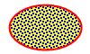
using the following code:
Dim bitmap As New Aurigma.GraphicsMill.Bitmap( _
 Aurigma.GraphicsMill.RgbColor.White, 100, 60, _
 Aurigma.GraphicsMill.PixelFormat.Format24bppRgb)

Dim graphics As System.Drawing.Graphics = bitmap.GetGdiplusGraphics()
graphics.SmoothingMode = System.Drawing.Drawing2D.SmoothingMode.AntiAlias

Dim brush As New System.Drawing.Drawing2D.HatchBrush( _
 System.Drawing.Drawing2D.HatchStyle.LargeConfetti, _
 System.Drawing.Color.Blue, System.Drawing.Color.Yellow)

graphics.FillEllipse(brush, 10, 5, 80, 50)

Dim pen As New System.Drawing.Pen(System.Drawing.Color.FromArgb(200, 255, 0, 0), 2)

graphics.DrawEllipse(pen, 10, 5, 80, 50)
Aurigma.GraphicsMill.Bitmap bitmap = new Aurigma.GraphicsMill.Bitmap(
    Aurigma.GraphicsMill.RgbColor.White, 100, 60,
    Aurigma.GraphicsMill.PixelFormat.Format24bppRgb);

System.Drawing.Graphics graphics = bitmap.GetGdiplusGraphics();
graphics.SmoothingMode = System.Drawing.Drawing2D.SmoothingMode.AntiAlias;

System.Drawing.Drawing2D.HatchBrush brush =
    new System.Drawing.Drawing2D.HatchBrush(System.Drawing.Drawing2D.HatchStyle.LargeConfetti,
    System.Drawing.Color.Blue, System.Drawing.Color.Yellow);

graphics.FillEllipse(brush, 10, 5, 80, 50);

System.Drawing.Pen pen = new System.Drawing.Pen(
    System.Drawing.Color.FromArgb(200, 255, 0, 0), 2);

graphics.DrawEllipse(pen, 10, 5, 80, 50);