Affine and Projective Transformations
Geometrical raster transformations such as scaling, rotating, skewing, and perspective distortion are very common transformation effects. All of them are implemented as linear transformation which are well-investigated in linear algebra. This topic descibes how to apply such transformations with Graphics Mill for .NET.
General Information
In mathematics, a linear transformation is a function that maps one vector space into another and is often implemented by a matrix. A mapping is considered to be a linear transformation if it preserves vector addition and scalar multiplication. To apply a linear transformation to a vector (i.e. coordinates of one point, in our case - x and y values of a pixel), it is necessary to multiply this vector by a matrix which represents the linear transform. As an output you will get a vector with transformed coordinates.
Two classes of linear transformations - projective and affine. Affine transformations are the particular case of the projective ones. Both of the transformations can be represented with the following matrix:

Where:
-
 is a rotation matrix. This matrix defines the kind of the transformation that will be performed:
scaling, rotation, and so on.
is a rotation matrix. This matrix defines the kind of the transformation that will be performed:
scaling, rotation, and so on. -
 is the
translation vector. It simply moves the points.
is the
translation vector. It simply moves the points. -
 is the
projection vector. For affine transformations all elements of this vector is always equal to 0.
is the
projection vector. For affine transformations all elements of this vector is always equal to 0.
If x and y are the coordinates of a point, the transformation can be done by the simple multiplication:
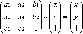
Here, x' and y' are the coordinates of the transformed point.
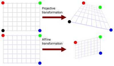
The projective transformation shows how the perceived objects change when the view point of the observer changes. This transformation allows creating perspective distortion. The affine transformation is used for scaling, skewing and rotation. Graphics Mill for .NET supports both these classes of transformations.
Difference Between Projective and Affine Transformations
The sole difference between these two transformations is in the last line of the transformation matrix. For affine transformations, the first two elements of this line should be zeros. But this leads to different properties of the two operations:
- The projective transformation does not preserve parallelism, length, and angle. But it still preserves collinearity and incidence.
- Since the affine transformation is a special case of the projective transformation, it has the same properties. However unlike projective transformation, it preserves parallelism.
Projective transformation can be represented as transformation of an arbitrary quadrangle (i.e. system of four points) into another one. Affine transformation is a transformation of a triangle. Since the last row of a matrix is zeroed, three points are enough. The image below illustrates the difference.
Linear transformation are not always can be calculated through a matrix multiplication. If the matrix of transformation is singular, it leads to problems. The transformation matrix is singular when it represents non-convex quadrangle. The shape is convex when each point which lies between two of points belonging to this shape is also belongs to the same shape. Speaking simpler, if
- the quadrangle is self-intersecting,
- or - - some vertex lies "inside" the quadrangle,
- or - - some vertices are situated in the same point,
this quadrangle is non-convex. This figure demonstrates some examples of non-convex quadrangles:
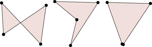
When you carry out linear transformation, make sure that it will not be singular. Graphics Mill for .NET is not able to apply such transformations.
How to Apply Affine Transformations
Generally, if you want to apply the transformation to the bitmap, you have to calculate the transformation matrix components and pass the matrix to the instance of the ApplyMatrixTransform class. Fortunately, Graphics Mill for .NET can do all math for you. You just pass sets of source and destination points and the matrix is automatically generated. Use the Matrix.FromAffinePoints method or initialize the existing instance of the Matrix class with the Matrix.FillFromAffinePoints method.
Suppose you have the following image:

The code below shows how to skew this image.
Dim bitmap As New Aurigma.GraphicsMill.Bitmap("C:\image.jpg")
Dim source As System.Drawing.PointF() = { _
    New System.Drawing.PointF(0.0F, 0.0F), _
    New System.Drawing.PointF(0.0F, 80.0F), _
    New System.Drawing.PointF(80.0F, 0.0F)}

Dim target As System.Drawing.PointF() = { _
    New System.Drawing.PointF(20.0F, 0.0F), _
    New System.Drawing.PointF(0.0F, 80.0F), _
    New System.Drawing.PointF(80.0F, 0.0F)}

Dim matrix As Aurigma.GraphicsMill.Transforms.Matrix = _
    Aurigma.GraphicsMill.Transforms.Matrix.FromAffinePoints(source, target)

Dim transform As New _
    Aurigma.GraphicsMill.Transforms.ApplyMatrixTransform(matrix)

transform.ApplyTransform(bitmap)
Aurigma.GraphicsMill.Bitmap bitmap = new Aurigma.GraphicsMill.Bitmap(
    @"C:\image.jpg");

System.Drawing.PointF [] source = {
    new System.Drawing.PointF(0f, 0f),
    new System.Drawing.PointF(0f, 80f),
    new System.Drawing.PointF(80f, 0f)};

System.Drawing.PointF [] target = {
    new System.Drawing.PointF(20, 0f),
    new System.Drawing.PointF(0f, 80f),
    new System.Drawing.PointF(80f, 0f)};

Aurigma.GraphicsMill.Transforms.Matrix matrix =
    Aurigma.GraphicsMill.Transforms.Matrix.FromAffinePoints(
    source, target);

Aurigma.GraphicsMill.Transforms.ApplyMatrixTransform transform =
    new Aurigma.GraphicsMill.Transforms.ApplyMatrixTransform(matrix);

transform.ApplyTransform(bitmap);
Here is the image that will be produced:

For base affine transformations such as scale and rotate, Graphics Mill for .NET already features special classes:
- Aurigma.GraphicsMill.Transforms.Resize - scale transformation.
- Aurigma.GraphicsMill.Transforms.Rotate - rotate transformation.
It is recommended to use them for scale and rotate operations.
How to Apply Projective Transformations
To create the matrix for the projective transformation, use the Matrix.FromProjectivePoints method. To initialize the existing instance of the Matrix class, use the Matrix.FillFromProjectivePoints method.
Be careful when choosing destination points. As the transformation matrix should be non-singular, do not specify points that form a self-intersecting quadrangle.
Here is an example of perspective distortion effect.
Dim bitmap As New Aurigma.GraphicsMill.Bitmap("C:\image.jpg")
Dim source As System.Drawing.PointF() = { _
   New System.Drawing.PointF(0.0F, 0.0F), _
   New System.Drawing.PointF(0.0F, bitmap.Height), _
   New System.Drawing.PointF(bitmap.Width, bitmap.Height), _
   New System.Drawing.PointF(bitmap.Width, 0.0F)}

Dim target As System.Drawing.PointF() = { _
    New System.Drawing.PointF(0.0F, 0.0F), _
    New System.Drawing.PointF(0.0F, bitmap.Height), _
    New System.Drawing.PointF(bitmap.Width * 0.75F, bitmap.Height - 50.0F), _
    New System.Drawing.PointF(bitmap.Width * 0.75F, 80.0F)}


Dim matrix As Aurigma.GraphicsMill.Transforms.Matrix = _
    Aurigma.GraphicsMill.Transforms.Matrix.FromProjectivePoints(source, target)

Dim transform As New _
    Aurigma.GraphicsMill.Transforms.ApplyMatrixTransform(matrix)

transform.ApplyTransform(bitmap)
Aurigma.GraphicsMill.Bitmap bitmap = new Aurigma.GraphicsMill.Bitmap(
    @"C:\image.jpg");

System.Drawing.PointF [] source = {
    new System.Drawing.PointF(0f, 0f),
    new System.Drawing.PointF(0f, bitmap.Height),
    new System.Drawing.PointF(bitmap.Width, bitmap.Height),
    new System.Drawing.PointF(bitmap.Width, 0f)};

System.Drawing.PointF [] target = {
    new System.Drawing.PointF(0f, 0f),
    new System.Drawing.PointF(0f, bitmap.Height),
    new System.Drawing.PointF(bitmap.Width * 0.75f, bitmap.Height - 50f),
    new System.Drawing.PointF(bitmap.Width * 0.75f, 80f)};

Aurigma.GraphicsMill.Transforms.Matrix matrix =
    Aurigma.GraphicsMill.Transforms.Matrix.FromProjectivePoints(
    source, target);

Aurigma.GraphicsMill.Transforms.ApplyMatrixTransform transform =
    new Aurigma.GraphicsMill.Transforms.ApplyMatrixTransform(matrix);

transform.ApplyTransform(bitmap);
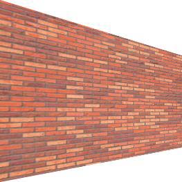
The image that will be produced will look as follows (resized version).
See Also
Reference
- ApplyMatrixTransform Class
- Matrix Class
- Matrix.FromAffinePoints Overload
- Matrix.FillFromAffinePoints Overload
- Matrix.FromProjectivePoints Overload
- Matrix.FillFromProjectivePoints Overload