Graphics: Drawing Images and Geometric Shapes
The article below is devoted to the basic aspects of using the drawing engine in Graphics Mill. Reading this article will help you become familiar with:
- The concept of Graphics, how to draw on bitmaps, and how to create PDF and EPS files.
- How to use pens and brushes for drawing geometric shapes.
- How to utilize drawing operations within the engine. Drawing images, curves, and shapes.
- What the clipping path is and how to apply it while drawing.
Graphics. Drawing on Bitmaps. Creating PDF and EPS.
The Aurigma.GraphicsMill.AdvancedDrawing namespace represents the drawing API in Graphics Mill. It includes classes allowing the creation of images of any complexity. All drawing operations are represented by the AdvancedDrawing.Graphics class that can be created from the following types of objects:
-
Bitmap. AdvancedDrawing allows drawing on images with any pixel format supported by Graphics Mill, except for indexed formats. Even extended formats (16 bits per channel), CMYK, and formats with alpha channels are handled correctly. The following snippet illustrates how to get Graphics from Bitmap:
C#using (var bitmap = new Bitmap(640, 480, PixelFormat.Format24bppRgb, RgbColor.White)) { var graphics = bitmap.GetAdvancedGraphics(); } -
PdfWriter allows for creating multi-page PDF documents and filling each page with content using the drawing API (to learn more about how to work with PDF, read the Working with PDF topic). Here is the code creating Graphics from PdfWriter.
C#using (var pdfWriter = new PdfWriter("in.pdf")) { pdfWriter.AddPage(500, 500); var graphics = pdfWriter.GetGraphics(); } -
EpsWriter is a class for creating EPS files (to learn more about how to work with EPS, read the Working with EPS topic). The following snippet shows how to get Graphics from EpsWriter:
C#using (var epsWriter = new EpsWriter("in.eps", 640, 480)) { var graphics = epsWriter.GetGraphics(); }
Pens and Brushes
Pen and Brush are two centerpiece objects needed for drawing graphics shapes. Pens are used for drawing lines, outlining shapes, or delineating other geometric objects. Whereas brushes are used for filling areas, such as filled shapes and text.
Line Color and Width
Pen allows you to specify an outline color via the
Pen.Color property and the outline width via the
Pen.Width property. The default value of
Width is 1.0,
whereas Color should always be passed to a constructor when initializing
a Pen instance.
The following snippet draws two lines:

using (var bitmap = new Bitmap(100, 60, PixelFormat.Format24bppRgb, RgbColor.White))
using (var graphics = bitmap.GetAdvancedGraphics())
{
    var redPen = new Pen(RgbColor.Red, 8);
    graphics.DrawLine(redPen, 10, 5, 90, 55);

    var bluePen = new Pen(RgbColor.Blue, 8);
    graphics.DrawLine(bluePen, 10, 55, 90, 5);

    bitmap.Save(@"Images\Output\out.png");
}
Dash Lines
By default, you draw solid lines. To draw dotted or dashed lines, specify the Pen.DashPattern property. This property is an array, and its elements are a sequence of painted and unpainted units. So, you are free to draw lines of any dash style.
For example, the following snippet draws dashed, dotted, and dash-dot lines:

using (var bitmap = new Bitmap(160, 80, PixelFormat.Format24bppRgb, RgbColor.White))
using (var graphics = bitmap.GetAdvancedGraphics())
{
    // A dashed line
    var pen = new Pen(RgbColor.Red, 2);
    pen.DashPattern = new float[] { 8, 2 };
    graphics.DrawLine(pen, 20, 20, 140, 20);

    // A dotted line
    pen.Color = RgbColor.DarkOrange;
    pen.DashPattern = new float[] { 2 };
    graphics.DrawLine(pen, 20, 40, 140, 40);

    // A dash-dot line
    pen.Color = RgbColor.Green;
    pen.DashPattern = new float[] { 10, 2, 2, 2 };
    graphics.DrawLine(pen, 20, 60, 140, 60);

    bitmap.Save(@"Images\Output\out.png");
}
You can shift the dash pattern sequence via the Pen.DashOffset property.
Solid Brushes
SolidBrush has the SolidBrush.Color property that specifies the color of the filled area.
The following snippet illustrates how to create a yellow rectangle having a green outline:
using (var bitmap = new Bitmap(160, 120, PixelFormat.Format24bppRgb, RgbColor.White))
using (var graphics = bitmap.GetAdvancedGraphics())
{
    graphics.DrawRectangle(new Pen(RgbColor.Green, 0.5f), 20, 20, 120, 80);
    graphics.FillRectangle(new SolidBrush(RgbColor.Yellow), 20, 20, 120, 80);
    bitmap.Save(@"Images\Output\out.png");
}
After launching this snippet, you will see the following result:

Gradient Brushes
To draw gradients, use the LinearGradientBrush class. You need to specify the ColorStops array that defines the colors of the filled area. Set two or more color stops with a color and its position within the filled area. The position is a relative value. To define a gradient direction, set StartPoint and EndPoint.
The following snippet illustrates how to create a gradient between blue, yellow, and red:

using (var bitmap = new Bitmap(300, 70, PixelFormat.Format24bppRgb, RgbColor.White))
using (var graphics = bitmap.GetAdvancedGraphics())
{
    var brush = new LinearGradientBrush();

    // Define the first color.
    var colorStop1 = new ColorStop();
    colorStop1.Color = RgbColor.Blue;
    colorStop1.Position = 0;

    // Define the second color.
    var colorStop2 = new ColorStop();
    colorStop2.Color = RgbColor.Yellow;
    colorStop2.Position = 0.75f;

    // Define the third color.
    var colorStop3 = new ColorStop();
    colorStop3.Color = RgbColor.Red;
    colorStop3.Position = 1;

    brush.ColorStops = new ColorStop[] { colorStop1, colorStop2, colorStop3 };

    // Define a direction of the gradient.
    brush.StartPoint = new System.Drawing.PointF(0, 0);
    brush.EndPoint = new System.Drawing.PointF(300, 0);

    graphics.FillRectangle(brush, 0, 0, 300, 70);

    bitmap.Save(@"Images\Output\out.png");

}
Drawing Graphic Elements
Graphics allows the drawing of the following elements:
Drawing Images
For drawing images, Graphics provides the DrawImage(Bitmap, RectangleF) method. This method draws an image from Bitmap in the specified rectangle, for example:
using (var bitmap = new Bitmap(225, 336, PixelFormat.Format24bppRgb, RgbColor.White))
using (var image = new Bitmap(@"Images\in.png"))
using (var graphics = bitmap.GetAdvancedGraphics())
{
    graphics.DrawImage(image, new System.Drawing.RectangleF(30, 30, 175, 286));
    bitmap.Save(@"Images\Output\out.png");
}
To make the source image fit the specified rectangle, Graphics Mill resizes the image, preserving its aspect ratio. If you need to preserve the original image's size, you should specify the location of the image:
using (var bitmap = new Bitmap(225, 336, PixelFormat.Format24bppRgb, RgbColor.White))
using (var image = new Bitmap(@"Images\in.png"))
using (var graphics = bitmap.GetAdvancedGraphics())
{
    graphics.DrawImage(image, 0, 0);
    bitmap.Save(@"Images\Output\out.png");
}
You can also draw an image from Pipeline using the overloaded DrawImage(Pipeline, RectangleF) method. This is useful when you need to transform your image before drawing, for instance, to rotate, resize, or crop it. The following snippet shows how to resize an image and then draw it in the PDF format:
using (var pdf = new PdfWriter(@"Images\Output\out.pdf"))
using (var image = new Bitmap(@"Images\in.png"))
using (var resize = new Resize(200, 150))
using (var graphics = pdf.GetGraphics())
{
    pdf.AddPage(200, 150);
    graphics.DrawImage(new Pipeline(image + resize), 0, 0);
    pdf.Close();
}
This snippet resizes the image without preserving its aspect ratio. You can choose whether or not to save an image's ratio using the Resize.ResizeMode property. You can also handle the quality of a resized image via the Resize.InterpolationMode property. For example, the following snippet demonstrates how to resize an image with high quality and preserve its aspect ratio:
using (var bitmap = new Bitmap(200, 150, PixelFormat.Format24bppRgb, RgbColor.White))
using (var image = new Bitmap(@"Images\in.png"))
using (var resize = new Resize(200, 150, ResizeInterpolationMode.High, ResizeMode.Fit))
using (var graphics = bitmap.GetAdvancedGraphics())
{
    graphics.DrawImage(new Pipeline(image + resize), 0, 0);
    bitmap.Save(@"Images\Output\out.png");
}
Drawing Lines and Curves
Graphics supports drawing the following line objects: lines, polylines, and Bezier curves. For all these types, you need to specify the outline color and width using a Pen instance. Let us discuss how to draw each line type.
Lines
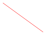
To create a line, use the DrawLine(Pen, PointF, PointF) method as the following snippet illustrates:
using (var bitmap = new Bitmap(160, 120, PixelFormat.Format24bppRgb, RgbColor.White))
using (var graphics = bitmap.GetAdvancedGraphics())
{
    graphics.DrawLine(new Pen(RgbColor.Red), 10, 10, 150, 110);
    bitmap.Save(@"Images\Output\out.png");
}
After launching this snippet you will see the following line:
Polylines
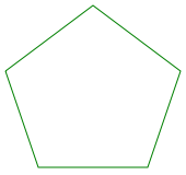
To create a polyline, use the DrawLines(Pen, PointF[]) method that draws a set of line segments specified by a PointF array. Remember, the ending point of a line is the starting point of the next line. The following snippet demonstrates how to draw a pentagon:
using (var bitmap = new Bitmap(170, 160, PixelFormat.Format24bppRgb, RgbColor.White))
using (var graphics = bitmap.GetAdvancedGraphics())
{
    System.Drawing.PointF[] points = {
        new System.Drawing.PointF(5,  65),
        new System.Drawing.PointF(85, 5),
        new System.Drawing.PointF(165, 65),
        new System.Drawing.PointF(135, 153),
        new System.Drawing.PointF(35,  153),
        new System.Drawing.PointF(5, 65)};
    graphics.DrawLines(new Pen(RgbColor.Green), points);
    bitmap.Save(@"Images\Output\out.png");
}
The polyline delineated pentagon looks as follows:
Bezier Curves
To create a Bezier curve, use the DrawBezier(Pen, PointF, PointF, PointF, PointF) method. A cubic Bezier curve is set by four points: a starting point, two control points specifying the curve direction, and an ending point (read the Working with Paths article discussing a cubic Bezier curve in detail). The following snippet illustrates how to draw a curve:
using (var bitmap = new Bitmap(160, 120, PixelFormat.Format24bppRgb, RgbColor.White))
using (var graphics = bitmap.GetAdvancedGraphics())
{
    graphics.DrawBezier(new Pen(RgbColor.Black), 10, 60, 40, 20, 70, 60, 100, 20);
    bitmap.Save(@"Images\Output\out.png");
}
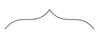
You can create a sequence of Bezier curves using the DrawBeziers(Pen, PointF[]) method. The ending point of one spline will be the starting point of the next one. Therefore, for splines, except for the first one in the array, you need to specify three points instead of four. The following snippet shows how to create a sequence of two splines:
using (var bitmap = new Bitmap(200, 80, PixelFormat.Format24bppRgb, RgbColor.White))
using (var graphics = bitmap.GetAdvancedGraphics())
{
    System.Drawing.PointF[] points = {
        new System.Drawing.PointF(10,  60),
        new System.Drawing.PointF(40, 20),
        new System.Drawing.PointF(70,  60),
        new System.Drawing.PointF(100, 20),
        new System.Drawing.PointF(130, 60),
        new System.Drawing.PointF(160, 20),
        new System.Drawing.PointF(190, 60)};
    graphics.DrawBeziers(new Pen(RgbColor.Black), points);
    bitmap.Save(@"Images\Output\out.png");
}
Please note that transition between two splines in a sequence is not smoothed, as you can see in the image below:
Drawing Graphics Shapes
Graphics supports drawing the following shapes: rectangles, ellipses, polygons, and paths. For all of them, you need to specify their outline color and width using a Pen instance. Now we will discuss how to draw these elements.
Rectangles
To draw a rectangle, use the DrawRectangle(Pen, RectangleF) method, passing the top left corner of the rectangle and its width and height as parameters:
using (var bitmap = new Bitmap(80, 80, PixelFormat.Format24bppRgb, RgbColor.White))
using (var graphics = bitmap.GetAdvancedGraphics())
{
    graphics.DrawRectangle(new Pen(RgbColor.Blue), new System.Drawing.Rectangle(10, 10, 60, 60));
    bitmap.Save(@"Images\Output\out.png");
}
You can draw several rectangles at a time using the DrawRectangles(Pen, RectangleF[]) method, which accepts an array of RectangleF.
Ellipses
To draw an ellipse, you need to specify a rectangle bounding the ellipse as a parameter of the DrawEllipse(Pen, RectangleF) method:
using (var bitmap = new Bitmap(80, 80, PixelFormat.Format24bppRgb, RgbColor.White))
using (var graphics = bitmap.GetAdvancedGraphics())
{
    graphics.DrawEllipse(new Pen(RgbColor.Blue), new System.Drawing.RectangleF(10, 10, 60, 60));
    bitmap.Save(@"Images\Output\out.png");
}
You can also draw several ellipses at a time using the DrawEllipses(Pen, RectangleF[]) method, which accepts an array of RectangleF.
Polygons
To draw a polygon, use the DrawPolygon(Pen, PointF[]) method, which accepts an array of vertices as the argument:
using (var bitmap = new Bitmap(170, 160, PixelFormat.Format24bppRgb, RgbColor.White))
using (var graphics = bitmap.GetAdvancedGraphics())
{
    System.Drawing.PointF[] points = {
        new System.Drawing.PointF(5,  55),
        new System.Drawing.PointF(85, 5),
        new System.Drawing.PointF(165, 55),
        new System.Drawing.PointF(135, 153),
        new System.Drawing.PointF(35,  153)};
    graphics.DrawPolygon(new Pen(RgbColor.Blue), points);
    bitmap.Save(@"Images\Output\out.png");
}
Paths
To draw a path on a Graphics object, use the Graphics.DrawPath(Pen, Path) method as shown below. If you do not know how to work with paths in Graphics Mill, read the Working with Paths article.
using (var bitmap = new Bitmap(170, 160, PixelFormat.Format24bppRgb, RgbColor.White))
using (var graphics = bitmap.GetAdvancedGraphics())
using (var path = new Path())
{
    path.DrawRectangle(new System.Drawing.RectangleF(75, 75, 75, 35));
    graphics.DrawPath(new Pen(RgbColor.Green), path);
    bitmap.Save(@"Images\Output\out.png");
}
Filling Figures
All figures discussed in the previous paragraph are drawn as outline shapes. Here, we will demonstrate methods of the Graphics class that draws filled elements:
- The FillRectangle(Brush, RectangleF) method fills a rectangle.
- The FillEllipse(Brush, RectangleF) method fills an ellipse.
- The FillPolygon(Brush, PointF[]) method fills a polygon.
- The FillBezier(Brush, PointF, PointF, PointF, PointF) method fills a Bezier curve.
- The FillPath(Brush, Path) method fills a path.
All these methods accept a Brush class instance as a parameter specifying a figure color.
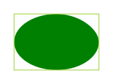
The following snippet demonstrates how to draw a filled ellipse and its bounded rectangle:
using (var bitmap = new Bitmap(160, 120, PixelFormat.Format24bppRgb, RgbColor.White))
using (var graphics = bitmap.GetAdvancedGraphics())
{
    graphics.FillEllipse(new SolidBrush(RgbColor.Green), new System.Drawing.RectangleF(20, 20, 120, 80));
    graphics.DrawRectangle(new Pen(RgbColor.YellowGreen), new System.Drawing.RectangleF(20, 20, 120, 80));
    bitmap.Save(@"Images\Output\out.png");
}
Here is the result of this snippet:
Clipping Path
The clipping path is a technique for cutting out a part of an image that is outside of a given vector path (to learn more about paths, read the Working with Paths article). For example, using a clipping path you can select an area of the image and put it over a new background. Graphics instances can have one or more clipping paths set in the Graphics.ClippingPaths property. While drawing with the Graphics object, the drawing region is defined by the path specified in this property. Everything drawn outside the given paths will not have any effect on the resulting image.
Assume that you have two images:

Let us say the first image contains a clipping path delineating the star (e.g. in Adobe Resources). We need to downsize the star and put it on the Christmas tree as follows:

Here is the algorithm that performs the task:
- Open the image with the star using ImageReader.
- Extract the clipping path from the loaded image and copy it to an AdvancedDrawing.Path instance.
- Resize the path. It should have the same size as the star on the Christmas tree.
- Move the resized path to the appropriate position.
- Add the path to the Graphics.ClippingPaths collection of Graphics created for the Christmas tree image.
- Resize the image of the star and use the Graphics.DrawImage(Pipeline, Single, Single) method to draw it on the Christmas tree.
According to the algorithm, we need to resize and translate the path. The AdvancedDrawing.Path class provides the ApplyTransform(Matrix) method for manipulating the path. This method accepts a Matrix instance as an argument. In turn, Matrix provides methods such as Translate, Scale, Rotate, etc., which perform transformations. Make sure that you apply the same transformations on the original "star" image as on the clipping path extracted from it. Otherwise, the path and the clipping path will not match. Here is the code based on the algorithm:
using (var reader = ImageReader.Create(@"Images\star.psd"))
using (var bitmap = new Bitmap(@"Images\conifer.png"))
using (var resize = new Resize(reader.Width / 4, reader.Height / 4))
using (var graphics = bitmap.GetAdvancedGraphics())
{
    var path = Path.Create(reader.ClippingPaths[0].CreateGraphicsPath(reader.Width, reader.Height));
    var m = new System.Drawing.Drawing2D.Matrix();
    m.Translate(85, 60);
    m.Scale(0.25f, 0.25f);
    path.ApplyTransform(m);

    graphics.ClippingPaths.Add(path);
    graphics.DrawImage(new Pipeline(reader.Frames[0] + resize), 43, 39);

    bitmap.Save(@"Images\Output\out.png");
}
See Also
Reference
- Aurigma.GraphicsMill.AdvancedDrawing Namespace
- AdvancedDrawing.Graphics Class
- Bitmap Class
- PdfWriter Class
- EpsWriter Class
- Pen Class
- SolidBrush Class
- Path Class